Selecting a 9V guitar pedal power adapter looks straightforward until the adapter becomes part of an actual pedalboard.
A 9V output alone does not determine compatibility. For guitar effects, polarity, connector dimensions, current capacity, output ripple, switching noise, grounding, cable design, and the way multiple pedals share power can all influence system performance.
This matters particularly for pedal manufacturers, audio-equipment brands, sourcing teams, and engineers developing products for commercial distribution. An adapter that powers a pedal successfully on the bench may still create audible noise in a high-gain signal chain or behave differently when several effects are connected through a daisy chain.
For most conventional 9V pedals, center-negative polarity remains the most important starting point. From there, the power system should be evaluated as part of the complete audio application rather than as an independent accessory.
This guide focuses on the engineering and sourcing decisions that matter when specifying a 9V power adapter for guitar pedals.

Start With the Electrical Specification, Not Just “9V”
A useful sourcing specification should contain considerably more information than:
Output: 9V DC
For an OEM guitar pedal project, a more complete specification may look like this:
| Parameter | Example Requirement |
|---|---|
| Input | 100–240V AC, 50/60Hz |
| Output Voltage | 9V DC |
| Rated Current | 1A |
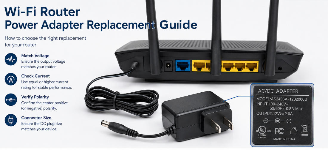
| Polarity | Center-negative |
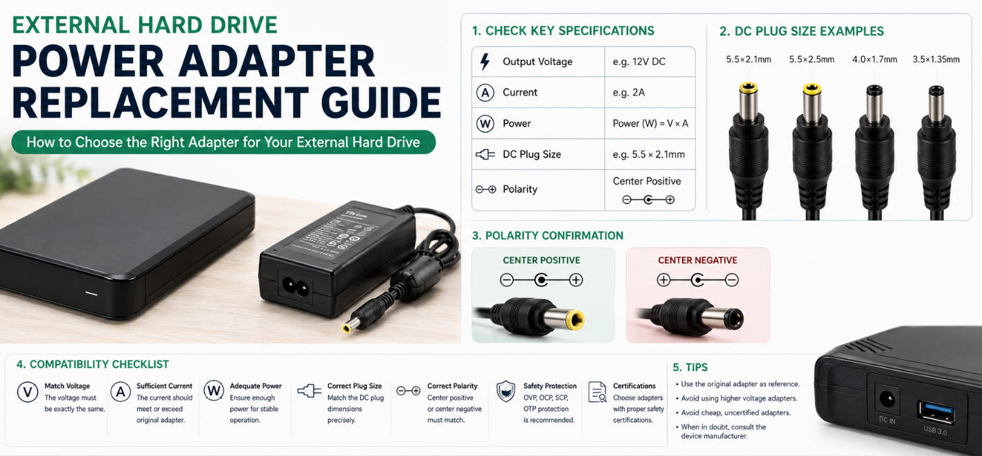
| DC Connector | 5.5 × 2.1mm |
| Cable Length | Defined by application |
| Regulation | Regulated DC output |
| Protection | OCP / OVP / SCP / OTP |
| Plug Version | US / EU / UK / AU, etc. |
| Noise Performance | Verified with target audio equipment |
These details reduce one of the most common sourcing risks: receiving an adapter that is electrically functional but unsuitable for the actual product.
A buyer should therefore evaluate a 9V guitar pedal power adapter from three perspectives:
electrical compatibility, audio performance, and deployment requirements.
All three should be confirmed before production approval.
Center-Negative Polarity Must Be Explicitly Defined
For guitar effects, polarity deserves special attention because the convention differs from many other DC-powered electronics.
A large number of conventional guitar pedals use:
Outer barrel: positive (+)
Inner contact: negative (−)
This is commonly referred to as center-negative polarity.
However, procurement teams should never treat center-negative as an automatic requirement simply because the product is a guitar pedal.
Exceptions exist.
The polarity requirement should be taken directly from the pedal circuit design and included in drawings, specifications, samples, and purchase documentation.
This is particularly important when an adapter manufacturer supplies products across multiple industries. A physically identical 5.5 × 2.1mm DC connector can be wired center-positive or center-negative.
Mechanical compatibility therefore does not confirm electrical compatibility.
For production projects, the adapter specification should state something similar to:
DC plug: 5.5 × 2.1mm, center-negative
rather than simply:
DC plug: 5.5 × 2.1mm
That single addition can prevent a potentially expensive sourcing error.
Consider Reverse-Polarity Protection at the Pedal Level
For pedal manufacturers, adapter polarity should not be the only layer of protection.
Reverse-polarity protection in the pedal input circuit can provide additional protection against users connecting an incompatible third-party adapter.
The implementation depends on the pedal architecture and design priorities, but the broader engineering principle is important:
Do not rely entirely on the external adapter to prevent incorrect field connections.
Consumers frequently mix adapters between devices, especially when barrel connectors appear identical.
The pedal and its recommended power adapter should therefore be designed as a system.
Voltage Accuracy Matters More Than the Label
A nominal “9V” marking does not tell an engineer how the supply behaves under real operating conditions.
Important parameters include:
- Output voltage tolerance
- Line regulation
- Load regulation
- Startup behavior
- Transient response
- Ripple and noise
- No-load voltage
- Full-load voltage
Older unregulated adapters could produce a noticeably higher voltage at light loads. Modern regulated switching adapters generally provide much tighter control, but the quality of regulation still varies by design.
For an audio application, voltage stability should be evaluated across realistic operating conditions.
For example, test the adapter with:
- Minimum expected pedal load
- Typical operating load
- Maximum rated load
- Startup conditions
- Rapid changes in current demand
Digital pedals deserve particular attention because processors, displays, relays, LEDs, and other circuits can create dynamic load changes.
A supply that appears stable with a simple resistive load may behave differently with the actual pedal electronics.
For buyers who need a broader framework for voltage, current, connector, and polarity selection, Szjialu’s AC DC power adapter selection guide provides additional engineering considerations that can be applied during the initial adapter specification process.
Current Capacity: Avoid Both Undersizing and Unnecessary Oversizing
The adapter’s rated current does not normally need to equal the pedal’s current consumption exactly.
If a pedal requires 200mA, for example, a properly regulated 9V 1A adapter can generally supply it because the pedal draws the current required by its circuit.
The important relationship is:
Adapter available current ≥ actual system current requirement
For OEM projects, however, selecting the current rating should involve more than simply adding a large safety margin.
An oversized adapter may increase:
- Physical dimensions
- Product cost
- Packaging requirements
- Shipping weight
- BOM cost
An undersized adapter can create more serious problems, including:
- Voltage drop
- Startup failure
- Digital resets
- Abnormal audio behavior
- Excessive adapter temperature
- Reduced long-term reliability
The objective is therefore not “the highest current possible.”
It is adequate current capacity with sensible engineering margin.
For example, Szjialu’s 12W Power Adapter AS1201A Series includes a 9V 1A configuration, providing a possible starting platform for applications requiring this output range. Connector type, polarity, cable configuration, certifications, and application-specific performance should still be defined according to the finished pedal design.
Daisy Chains Change the Power-System Requirements
A single-pedal application and a multi-pedal daisy-chain application should not automatically use the same qualification criteria.
With a daisy chain, several pedals share one adapter output.
Suppose a pedalboard contains:
| Device | Current Consumption |
|---|---|
| Tuner | 50mA |
| Compressor | 30mA |
| Overdrive | 20mA |
| Chorus | 80mA |
| Digital Delay | 250mA |
| Total | 430mA |
From a current-capacity perspective, a regulated 9V 1A supply appears more than adequate.
But 430mA < 1A does not prove that the complete system will be quiet.
This is where power-adapter selection for audio equipment becomes different from many ordinary electronic applications.
The pedals are not simply loads.
They are interconnected audio devices.
Their signal grounds, power grounds, internal switching circuits, and patch cables can interact.
Therefore, the question for a daisy-chain system is not only:
“Can the adapter provide enough current?”
It is also:
“Can these devices share the same power rail without creating audible interference?”
Why Daisy Chains Can Introduce Noise
In a conventional daisy chain, multiple pedals share the same DC output and common power ground.
At the same time, the pedals are interconnected by audio cables.
This creates multiple electrical paths between devices.
Depending on the pedal designs and the rest of the rig, shared power can contribute to hum or other unwanted noise.
The issue becomes more noticeable in systems combining different types of electronics.
For example:
Analog overdrive + analog compressor + analog distortion
may operate quietly from one shared adapter.
But adding:
digital delay + reverb + DSP-based modulation
can change the result significantly.
Digital pedals contain clocks, processors, switching circuits, converters, and other high-frequency electronics. Electrical noise generated inside one pedal may travel through a shared power rail and become audible elsewhere in the signal chain.
This is why a daisy-chain test should be performed using the intended pedal combination rather than evaluating the adapter only with one pedal at a time.
Isolation Solves a Different Problem Than Higher Current
One common mistake is attempting to solve pedalboard noise by purchasing an adapter with a larger current rating.
If a 1A supply creates noise, changing to a 2A supply will not necessarily improve anything.
Current capacity and electrical isolation address different problems.
A higher-current adapter helps when the existing supply cannot provide sufficient current.
Isolation helps when unwanted electrical interaction occurs between connected devices.
With genuinely isolated outputs, individual pedal outputs do not share the same direct power path.
This can reduce problems associated with:
- Ground loops
- Shared return currents
- Noise transfer between pedals
- Digital-to-analog interference
This distinction should also influence how power products are described.
A supply with multiple DC connectors is not automatically an isolated power supply.
If all outputs share the same electrical source, the arrangement behaves differently from individually isolated outputs.
For procurement documentation and product marketing, terms such as “multi-output” and “isolated output” should therefore not be used interchangeably.
Output Ripple and Switching Noise Need Audio-Level Evaluation
Modern switching power adapters provide major advantages in efficiency, size, universal AC input, and thermal performance.
But for guitar pedals, output quality deserves additional attention.
A switching adapter operates at frequencies far above mains frequency. If switching components and their harmonics are not adequately controlled, they may enter sensitive audio circuitry.
The audible result may appear as:
- High-frequency whine
- Buzz
- Hiss
- Clicking
- Modulated digital noise
- Increased background noise
This does not mean switching adapters are inherently unsuitable for guitar pedals.
A properly engineered switch-mode power supply can perform very well in audio applications.
The key is controlling:
ripple, conducted interference, radiated interference, common-mode noise, and load-dependent behavior.
For an OEM pedal project, reviewing only the adapter’s datasheet ripple specification may not be sufficient.
The more meaningful test is:
Adapter + pedal + amplifier/audio measurement system
under representative operating conditions.
Test Noise Under High-Gain Conditions
Noise qualification should reflect how guitar equipment is actually used.
A small amount of interference that appears insignificant in a basic bench measurement may become obvious when the signal passes through high-gain stages.
Consider testing the adapter with:
- Clean pedal bypass
- Pedal effect engaged
- High-gain distortion
- Multiple pedals connected
- Daisy-chain operation
- Digital and analog pedals combined
- Different AC input voltages
- Minimum and maximum expected loads
If the intended product will be sold internationally, AC input conditions should also represent the target markets.
A supply may be expected to operate across a universal input range, but EMC behavior and noise performance should still be validated under relevant conditions.
Cable Design Can Influence System Performance
The DC cable is sometimes treated as a cosmetic specification. For a pedal-power application, it should be considered part of the electrical system.
Important parameters include:
- Conductor gauge
- Cable length
- DC resistance
- Flexibility
- Connector retention
- Strain relief
- Shielding or filtering strategy where applicable
Longer or thinner cables create additional resistance.
As current increases, cable voltage drop also increases.
This becomes more important when one adapter powers several pedals through a daisy chain.
The relationship can be expressed simply as:
Voltage Drop = Current × Cable Resistance
A cable design that performs adequately at 100mA may behave differently when the same power path carries 800mA.
For OEM projects, cable length and conductor size should therefore be finalized before production validation rather than changed afterward as a packaging decision.
Connector Fit Should Be Verified With Production Hardware
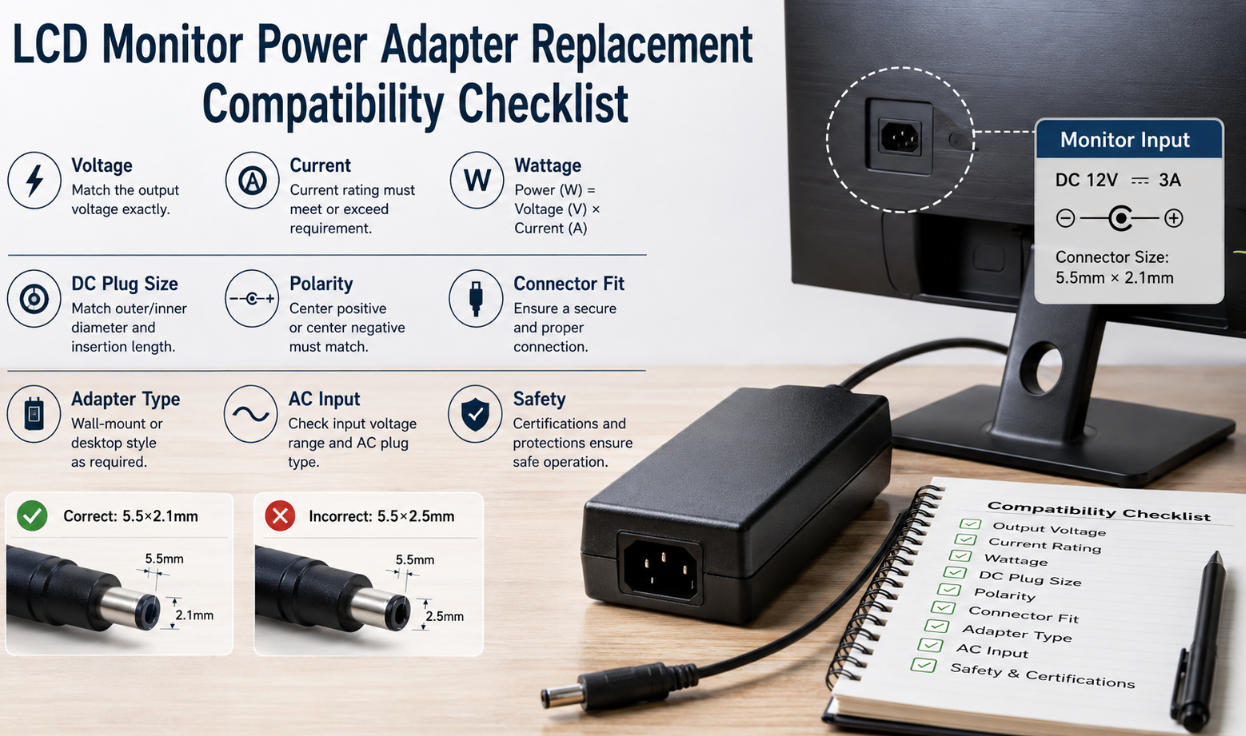
The common guitar-pedal barrel interface is often associated with a 5.5mm outer diameter and 2.1mm inner diameter, but buyers should never specify a connector based solely on industry convention.
Connector dimensions affect:
- Mechanical fit
- Contact reliability
- Insertion force
- Retention
- Intermittent power risk
A 5.5 × 2.5mm and 5.5 × 2.1mm connector can appear extremely similar to a non-specialist.
That makes detailed drawings and sample verification important.
During supplier qualification, test the actual adapter connector with production or production-equivalent pedal jacks.
Do not rely exclusively on nominal dimensions from two separate datasheets.
EMC Performance Should Be Considered at System Level
EMC compliance and audible noise are related engineering concerns, but they are not identical.
An adapter can satisfy regulatory EMC requirements and still produce an undesirable noise characteristic in a particular audio system.
Likewise, a pedal and adapter tested independently may behave differently after they are connected together.
For this reason, manufacturers should consider system-level testing involving:
AC mains → power adapter → guitar pedal → audio signal chain
This is particularly valuable for products intended for recording, professional stage use, or high-gain applications.
Potential areas to evaluate include:
- Conducted emissions
- Radiated emissions
- Immunity
- Output ripple
- Common-mode behavior
- Interaction with audio ground
- Performance near other switching equipment
The goal is not merely regulatory compliance.
The goal is regulatory compliance plus acceptable real-world audio performance.
Regional Plug Variants Matter for Global Pedal Brands
For brands distributing one pedal platform internationally, regional AC plugs can complicate SKU management.
Markets may require different plug configurations, including:
- US
- EU
- UK
- AU
- KR
- Other regional formats
One approach is to use separate fixed-plug adapters for each destination.
Another is to develop an interchangeable-plug platform where appropriate.
Each approach has trade-offs involving cost, certification, packaging, logistics, and user experience.
Szjialu’s broader power adapter range includes multiple external adapter configurations that can serve as a starting point when defining output voltage, regional plug style, connector, cable, and other OEM requirements.
For purchasing teams, these decisions should be made early because changing the plug architecture can affect certification scope and packaging design.
Protection Functions Should Be Part of the Specification
The low-voltage side may operate at only 9V, but the adapter remains a mains-powered product.
Protection requirements should therefore be included in supplier evaluation.
Depending on the adapter architecture, relevant protection functions can include:
OCP — Over-Current Protection
Helps protect the adapter when the connected load demands excessive current.
OVP — Over-Voltage Protection
Helps prevent abnormal output-voltage conditions from reaching the load.
SCP — Short-Circuit Protection
Important for DC cables and connectors that may experience accidental shorts.
OTP — Over-Temperature Protection
Provides additional protection when abnormal operating conditions cause excessive temperature.
Protection behavior should also be considered.
For example, purchasing and engineering teams may need to understand whether the supply uses hiccup protection, auto-recovery, latch-off behavior, or another protection strategy.
For broader information about external power supply protection and compliance considerations, see the Szjialu Power Adapter Safety Guide.
A Practical Qualification Process for OEM Buyers
Rather than approving a 9V guitar pedal power adapter from specifications alone, buyers can use a staged qualification process.
1. Confirm Electrical Requirements
Define:
- 9V DC output
- Output tolerance
- Required current
- Center-negative polarity
- DC connector dimensions
- Cable specification
2. Confirm Mechanical Requirements
Check:
- Plug fit
- Cable length
- Strain relief
- Adapter dimensions
- AC plug configuration
- Packaging limitations
3. Verify Protection and Compliance
Review:
- Required safety approvals
- EMC requirements
- Regional regulations
- OCP
- OVP
- SCP
- OTP where required
4. Test With the Actual Pedal
Measure performance under:
- Startup
- Idle
- Normal operation
- Maximum expected load
- Effect bypassed
- Effect active
5. Perform Audio Noise Testing
Listen and measure using representative amplifiers and signal chains.
Pay particular attention to high-gain conditions.
6. Test Multi-Pedal Operation
If daisy-chain use is expected, test realistic combinations of analog and digital pedals.
Do not assume that successful single-pedal operation guarantees successful pedalboard operation.
7. Validate Production Samples
After the engineering sample is approved, verify that pre-production and mass-production units maintain the required electrical, mechanical, and noise performance.
Final Engineering Considerations
For guitar-pedal applications, the most important specification is not simply 9V DC.
A production-ready power solution needs the correct combination of:
9V regulated output + sufficient current + center-negative polarity + correct DC connector + controlled ripple/noise + appropriate protection + suitable regional configuration.
When one adapter will power multiple pedals, another layer of evaluation becomes necessary.
A daisy chain may be entirely suitable for a group of compatible pedals, particularly simple analog effects with modest current consumption. But shared power can also allow noise generated by one device to affect another.
When that happens, additional current capacity is not necessarily the solution. Electrical isolation may be required.
For pedal manufacturers, audio brands, and purchasing teams, the most reliable approach is therefore to qualify the adapter as part of the complete system.
Szjialu provides configurable AC/DC power adapter solutions for OEM and ODM projects, including different output specifications, regional plug options, DC connectors, cable configurations, and protection requirements. For a 9V guitar pedal project, these parameters can be defined around the electrical and mechanical requirements of the finished product rather than treating the adapter as a generic off-the-shelf accessory.
For audio equipment, a power adapter should not merely make the product turn on.
It should allow the product to perform as designed—without becoming part of what the customer hears.